Analyzing the Electromagnetic Behavior of Negative Index Materials
There is considerable interest in the electromagnetic behavior of materials that have both permittivity and permeability with negative real parts, particularly in applications for reducing radar scattering. These materials have several names including Negative Index Materials (NIM), Double Negative Materials (DNG), Left-Handed Materials, and are a category of Metamaterials. This interest is based in large part on the availability of metamaterials with this characteristic. XFdtd, although a time domain solver, has the capability to make calculations for these materials using the frequency-dependent material models included with the software. This example illustrates this capability and presents some interesting results for these unusual materials.
The material under consideration has real permittivity and permeability values of -1 at 30 GHz. The imaginary parts of the permittivity and permeability are small at the frequency of interest to reduce losses. At 30GHz the material should have an impedance approximately equal to free space with low loss and negative phase velocity.
While XFdtd is intended for full 3D calculations, these figures were made for a 2D geometry, which is efficient for illustrating the behavior of these materials. The basic geometry is shown in Figure 1 and includes a rectangle that represents the 2D slab of material. At the right of the slab is a simple horn antenna fed by a waveguide with a 30 GHz voltage source. The antenna is tilted at a 20 degree angle with the slab normal. The voltage waveform is ramped in amplitude over the first cycle. The electric field is polarized perpendicular to the plane of the figures so the magnetic field is in the plane of incidence. A very small cell size is chosen to provide detailed field resolution in the images that follow. The fields displayed are instantaneous electric fields in a dB scale.
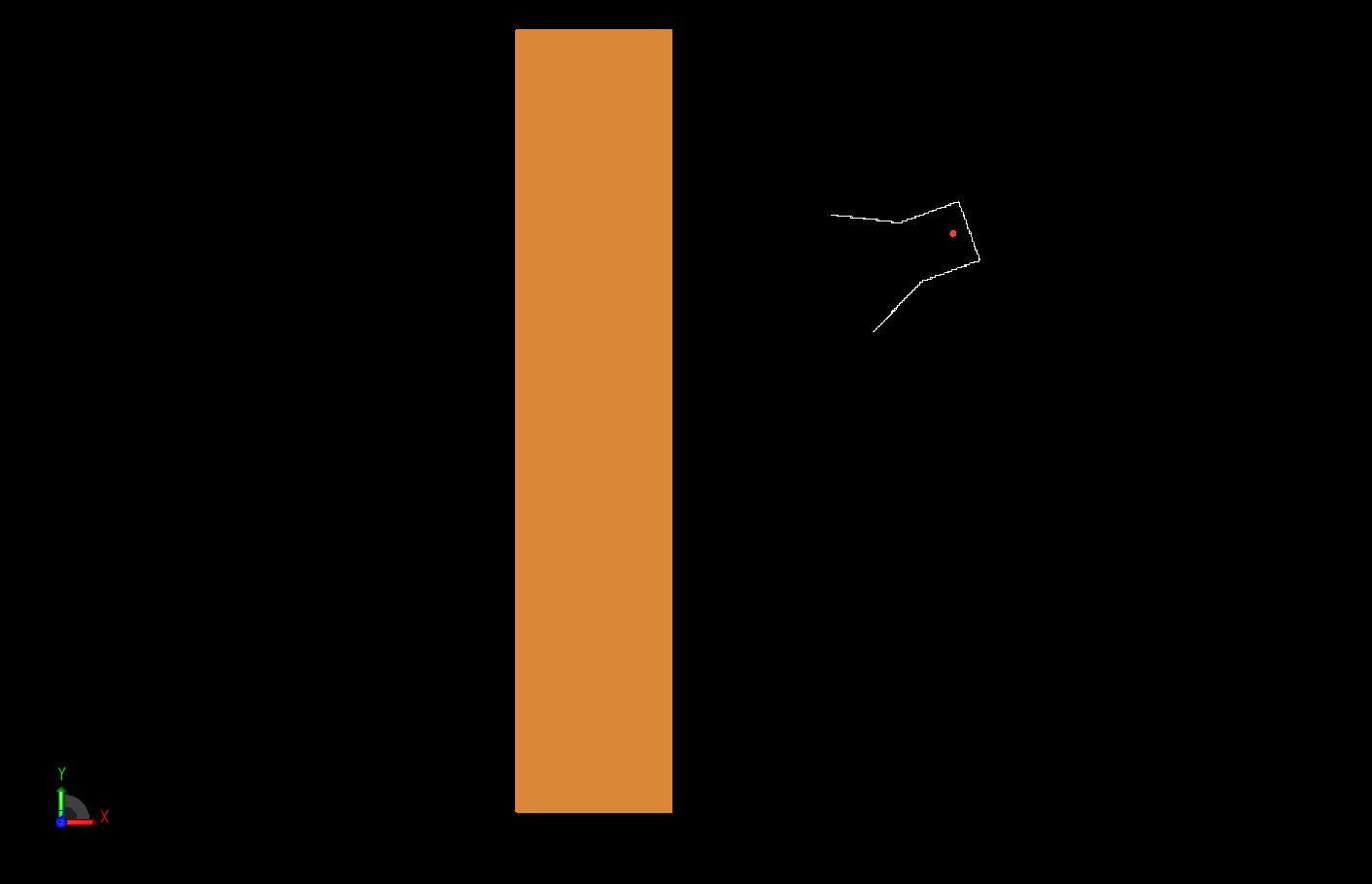
Figure 1: The basic two-dimensional geometry of the material slab and the tilted horn radiator.
There are three different materials considered in this example. First the slab is removed and the antenna radiates in free space as shown in Figure 2. This demonstrates the undisturbed fields emanating from the antenna horn.
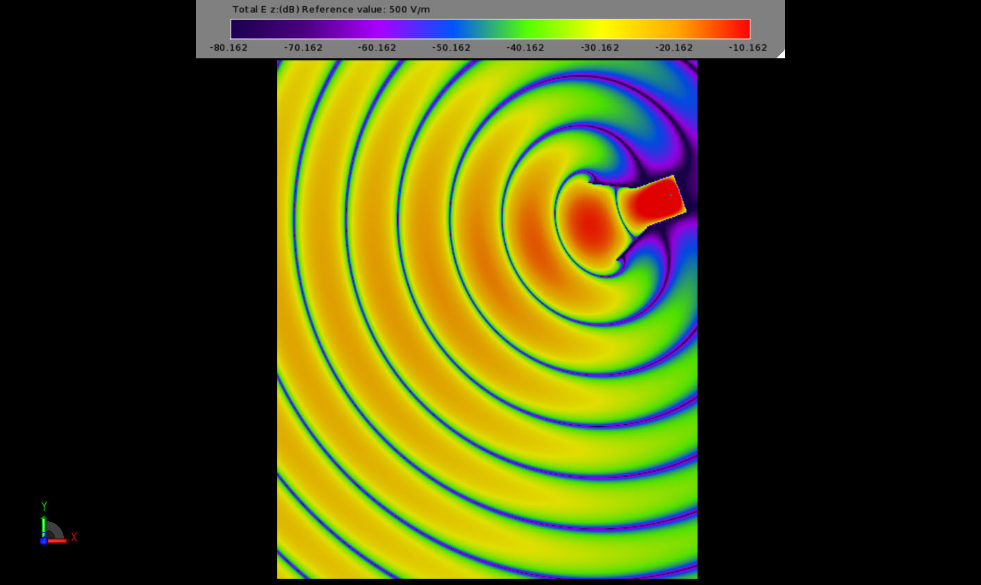
Figure 2: The field propagation in empty two-dimensional space from the horn radiator.
Next a dielectric slab with constant relative mu = epsilon = 4 is considered. This slab has the same impedance as free space so should have no reflections at its interfaces. The field interaction is shown in Figure 3 where the wavelength of the signal can be seen to compress within the material but no reflections are apparent from the surface.
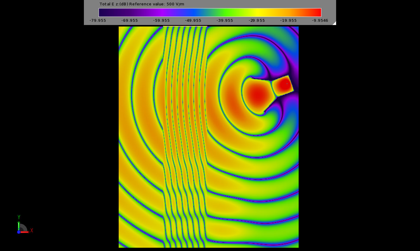
Figure 3: The field propagation through the impedance matching material with epsilon=mu=4. No reflections are seen from the material surface.
Finally, the negative index material is applied to the slab. This is done using a dual dielectric and magnetic frequency dependent model of the Drude form. The complex permittivity is shown plotted in Figure 4. An analogous plot for the permeability also exists. After assigning the material to the slab, the simulated fields are computed and can be seen in Figure 5.
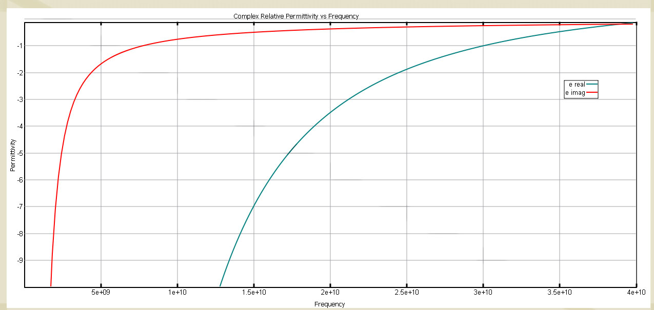
Figure 4: The Drude complex permittivity profile for the Negative Index Material with real permittivity = -1 at 30 GHz.
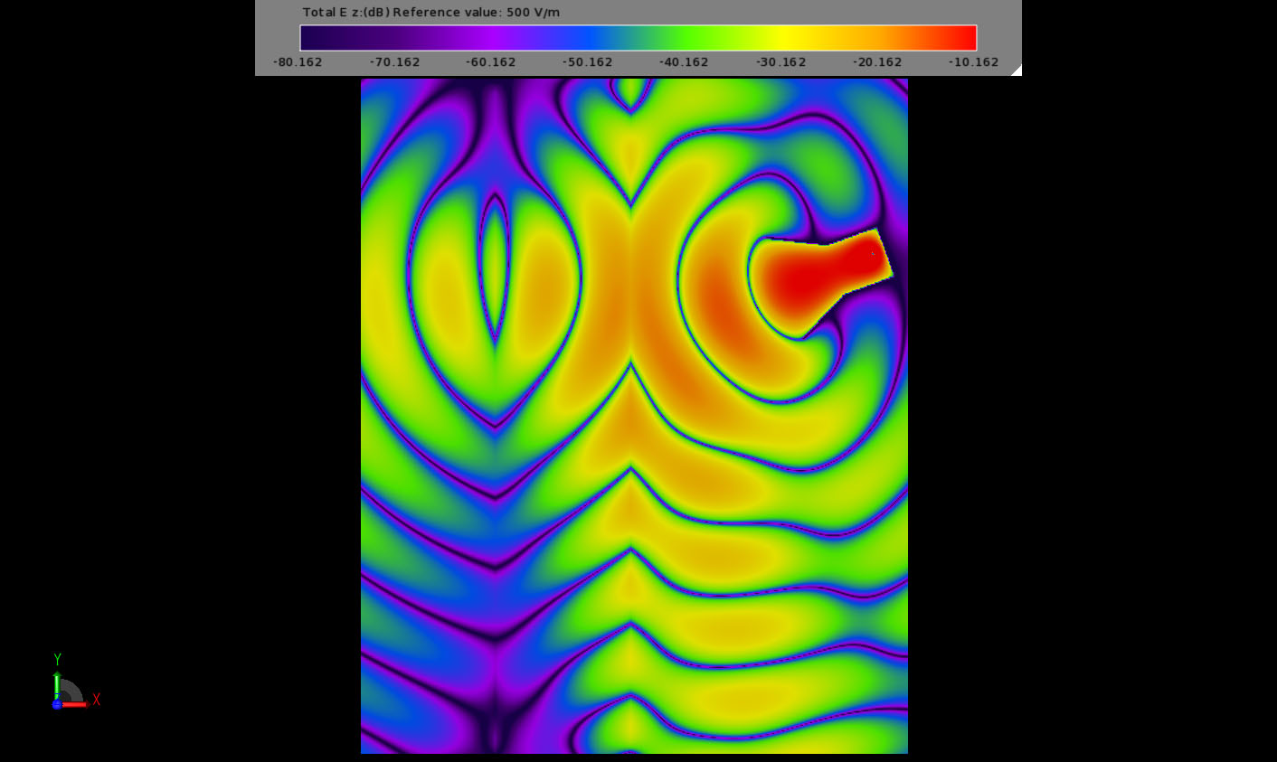
Figure 5: The late time field propagation through the NIM slab showing the unusual field distribution within the material.
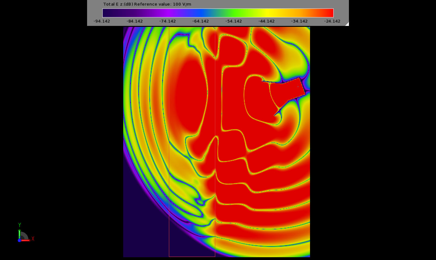
Consider the behavior as the electromagnetic energy interacts with the negative index material slab in Figures 6-11. Nulls in the transient electric field appear to travel faster in DNG than in free space but energy propagates through DNG at about (no greater than) the same speed as in free space. The direction of propagation in the DNG is tilted in the opposite direction as for a “normal” material. Early transient fields beyond slab show rapid spatial variations. After steady state is reached the wave fronts in the DNG appear to travel toward the source. This is best visualized by downloading the example and playing the field sequence movie within XFdtd.
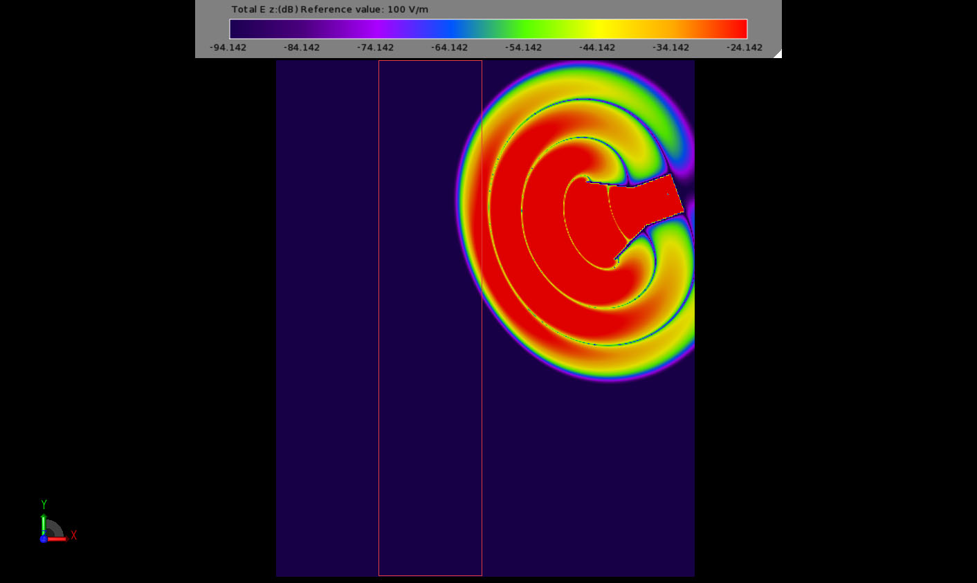
Figure 6: Early field interaction with the NIM slab.
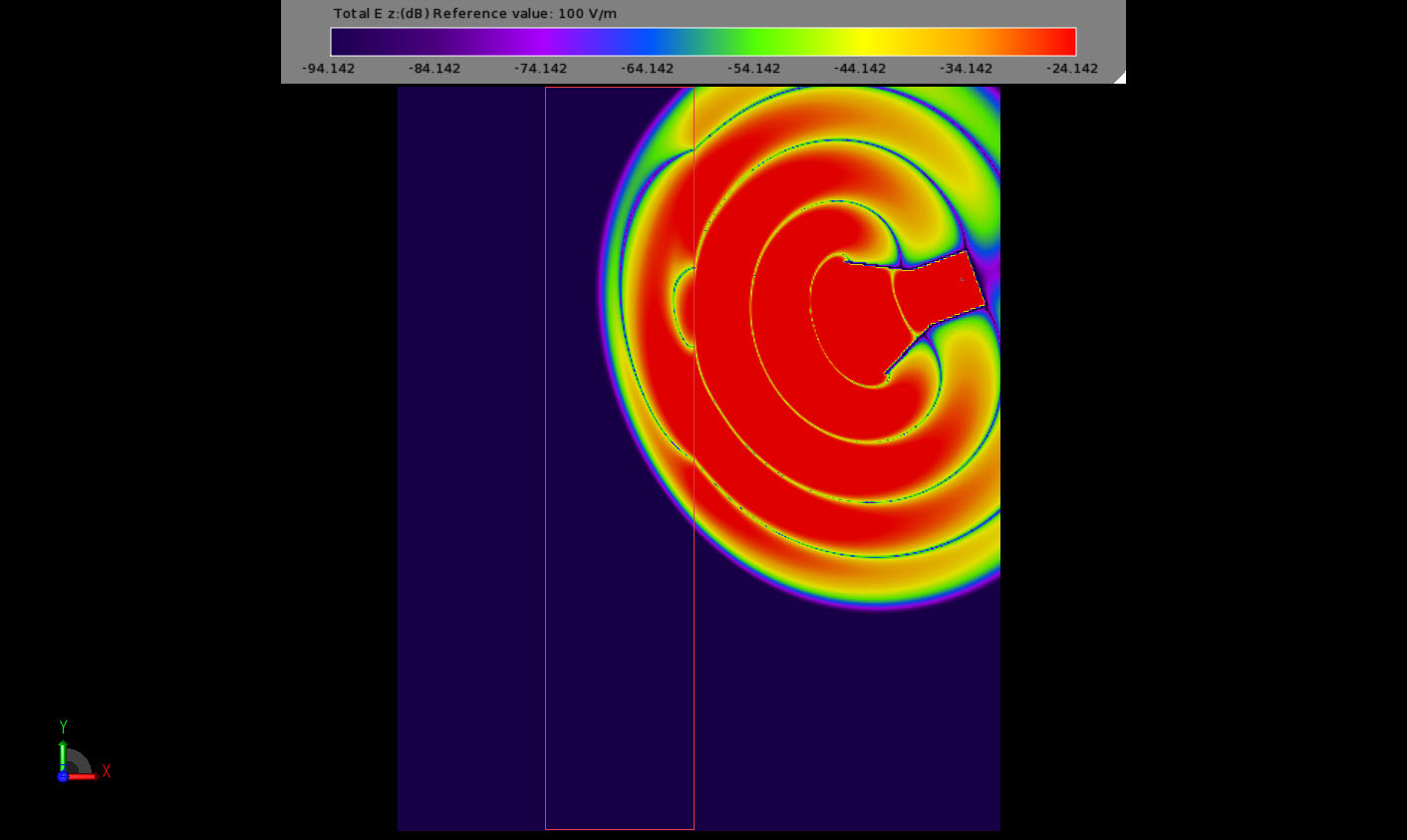
Figure 7: Step 2 of field interaction with the NIM slab.
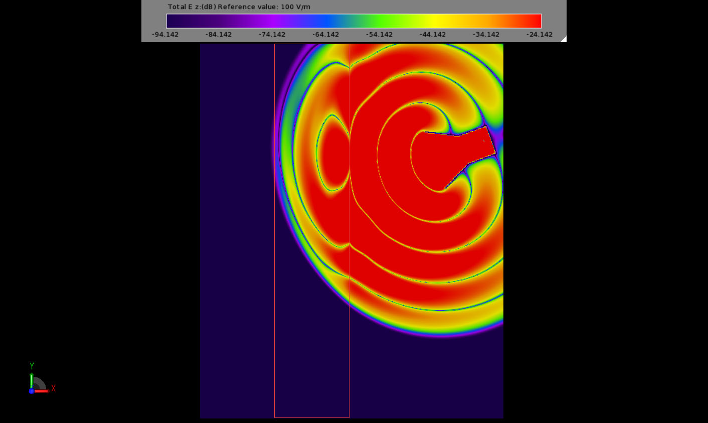
Figure 8: Step 3 of field interaction with the NIM slab.
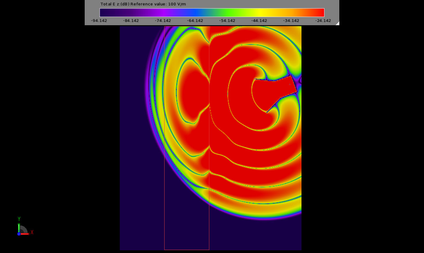
Figure 9: Step 4 of field interaction with the NIM slab.
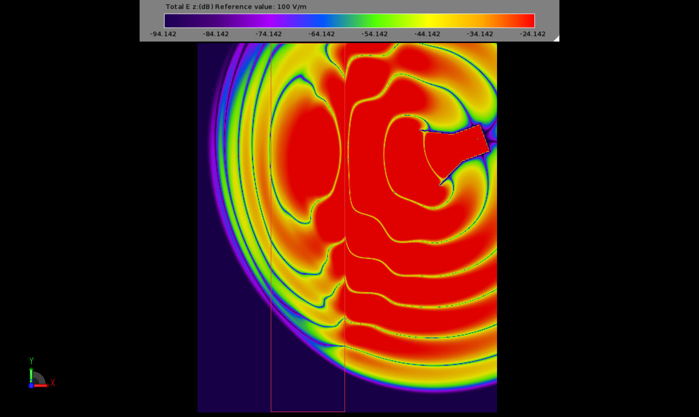
Figure 10: Step 5 of field interaction with the NIM slab.
