Anisotropic Sphere Scattering Analysis with Bistatic RCS Modeling
This example demonstrates the ability of XFdtd to simulate dielectric materials with off-diagonal terms in the permittivity tensor. The case in point here is the computation of bistatic radar cross section from an anisotropic sphere excited by a plane wave.
The sphere is chosen to have a size ka = 0.5 where k is the wave number given by 2π/λ, where λ is the free space wavelength. For this simulation, the frequency is chosen to be 300 MHz giving a wavelength of 1 m. In turn, the radius of the sphere will be 79.58 mm. The permittivity of the material under consideration for this example has a tensor in the frequency domain given by:

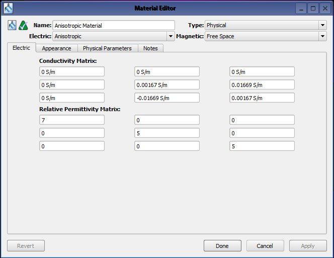
Figure 1: The XFdtd material editor with the anisotropic material defined.
At 300 MHz, the terms (5 - 0.1j) convert to a permittivity of 5 and a conductivity of 0.00167 S/m. Similarly the conductivity for the off-diagonal terms (+/- j) convert to a conductivity of +/- 0.01669 S/m. A view of this material entered into the XF7 material editor is shown in Figure 1. This material is slightly lossy due to the imaginary terms on the diagonal. The off-diagonal imaginary terms have opposite signs and therefore do not add loss to the material, but they do make it gyrotropic.
A sphere is created in XFdtd of the appropriate size and meshed in a 5mm grid. An incident plane wave with a frequency of 300 MHz is created to be incident from the -X direction (theta = 90 degrees, phi = 180 degrees) with the electric field Z polarized (theta direction). With this excitation, if the material were diagonally isotropic there would be no Y-polarized electric field.
For comparison, an initial calculation is made for an isotropic sphere with a permittivity of 5. The bistatic scattering patterns in the E and H planes are computed for the isotropic sphere and are shown in Figures 2 and 3. For the E-plane pattern, the angular variation is in theta around the XZ plane of the sphere and the wave is incident from 270 degrees. The H-plane pattern has variation in phi around the XY plane with the wave incident from the 180 degree direction. The co-polarized plots are visible in the figures but the cross-polarized signal is so small that it does not appear on the plots. This is as expected for the isotropic sphere.
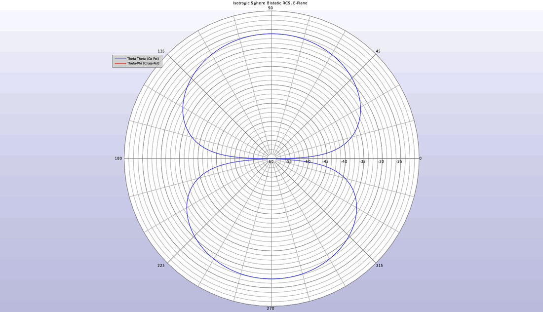
Figure 2: The bistatic RCS of the isotropic sphere in the E-plane showing only co-polarized scattering.
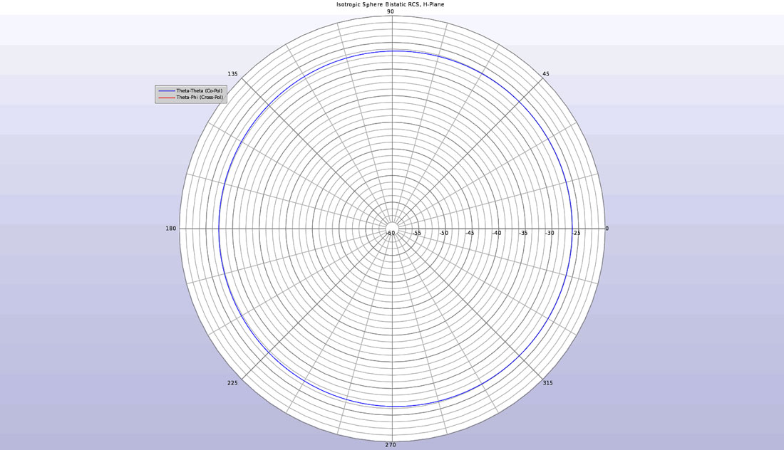
Figure 3: The bistatic RCS of the isotropic sphere in the H-plane showing only co-polarized scattering.
When the anisotropic sphere is substituted for the isotropic one, the resulting output is different. As can be seen in Figures 4 and 5, the bistatic scattering pattern shows a cross-polarized component in addition to the co-polarized signal. The cross polarized pattern is a result of the anisotropic nature of the material.
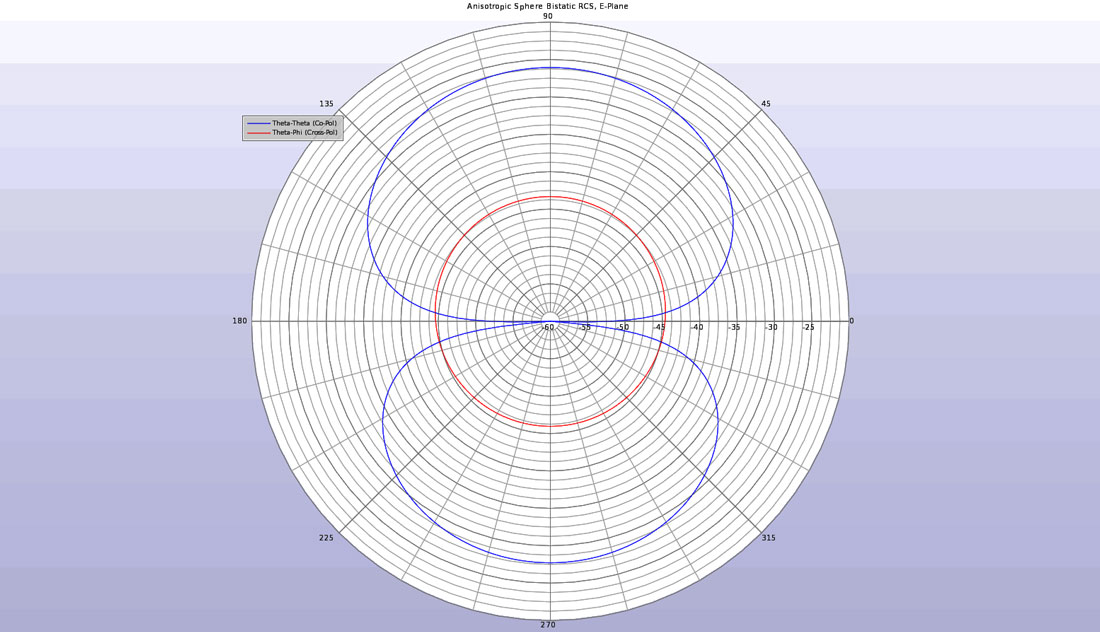
Figure 4: The bistatic RCS of the anisotropic sphere in the E-plane showing both co- and cross-polarized scattering.
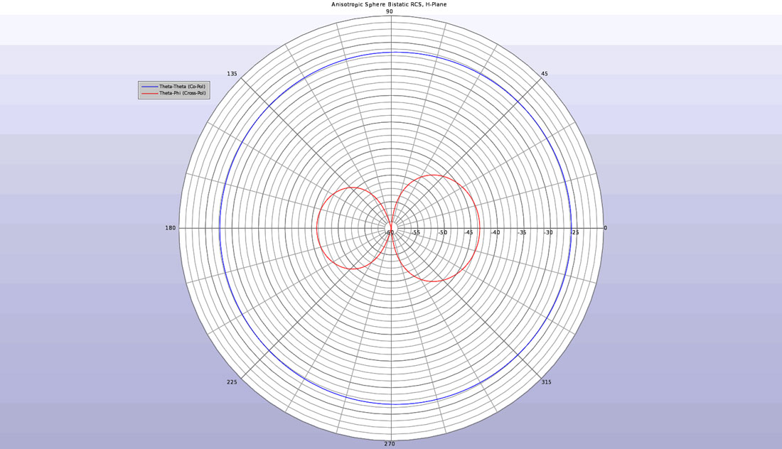
Figure 5: The bistatic RCS of the anisotropic sphere in the H-plane showing both co- and cross-polarized scattering.
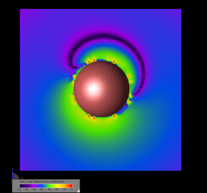
In the near-field, the Y-polarized electric field is visible for the anisotropic sphere. In Figure 6, the steady state field magnitude is displayed for the Y component of the field in the E-plane around the anisotropic sphere.
