Path Loss Comparison in Rosslyn, Virginia
In this example path loss predictions made with Wireless InSite's urban canyon and full 3-D propagation models are compared to measurements made in Rosslyn, Virginia by the group at AT&T Bell Laboratories between December of 1994 and February of 1996. These measurements were made at thousands of locations along the streets using street level and roof top transmitters. Many of the measurements were made within the approximately 500 meter square area of Rosslyn shown in Figure 1 in which many of the buildings are 10 stories or more in height. This section of Rosslyn is referred to below as the "high-rise" area. Measurements were also made in the "Colonial Terrace" area shown in Figure 2 which consists mostly of 3 to 4 story residential buildings. For the last round, the measurements were made in the mixed residential and commercial area south of Wilson Blvd shown in Figure 3.
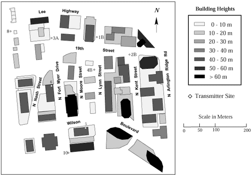
Figure 1: Plan View of the High-rise of Rosslyn Showing Many of the Transmitter Sites.
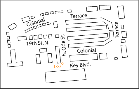
Figure 2: Plan View of the Colonial Terrace Area in Rosslyn Showing the Building Locations, Street Name and Transmitter Site 7.
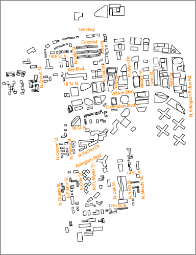
Figure 3: Building Geometry for Rosslyn, Virginia.
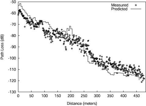
Fig. 4: Path loss along 19th St./Nash St. for Transmitter Site 2B at 900 MHz. The path starts near site 2B and ends at Wilson Blvd.
All the predictions presented here were totally blind, that is, the predictions were submitted to AT&T before Remcom had access to the measured path loss data. Additional information about how the measurements were made can be found in [1].
Most of the transmitter sites are shown in Figure 1. In addition to these, the location of site 7 is shown in Figure 2, and sites 11 and 12 are in Figure 3. For all street level sites, with the exception of site 4A, the transmitting antennas were supported by a tower at a height of 10 m above local ground. For site 4A the height was 3 m. For the roof top sites the directional transmitting antennas were located on buildings at sites 5 and 6 in Figure 1. These antennas were located 2 m above the building roofs and approximately 3 meters from the roof edge. The antenna height at site 5 was approximately 42 m above local ground, while site 6 was approximately 43 meters above local ground. As can be seen in Figure 1, these latter two heights are above many of the nearby buildings so that propagation over the buildings is important. The bore sight for transmitter antenna 5 was directly north and 5 degrees down from horizontal. Measurements were made with antenna 6 pointing northeast, east and southeast, with a 5-degree down-tilt from horizontal in all cases.
Measurements were made at 900 MHz and 1.9 GHz with all antennas vertically polarized. For the rooftop transmitters (5 and 6), the radiation patterns were highly directional with half-power beamwidth of about 50 and 30 for the 900 and 1900 MHz antennas, respectively. The pattern is included in the predicted path loss, as was the receiving antenna vertical dipole (sin) pattern. For the street level transmitters, the vertical antenna patterns were not included, and the horizontal patterns were omnidirectional. The receiving antenna was located on a van, with the antenna approximately 2.3 m above local ground.
Some typical prediction results using the urban canyon model for the transmitting antenna at site 2B at 900 MHz are shown in Figures 4-6. Figure 4 shows the measurements and predictions for the receiving van driven along 19th St./Nash St. From Figure 1 it can be seen that the first 225 m of this path is a line-of-sight (LOS) region, and the remainder must be reached by multiple reflection/diffraction. Results for Lynn St. and Moore St. are in Figure 5 and Figure 6, respectively. Both these paths contain a LOS region roughly between 200 m and 250 m with the remaining part of the path being reached by multiple reflection/diffraction. Some typical urban canyon comparisons to measurements for transmitter site 4B can be found in Figure 7 and Figure 8. A comparison to measurements for transmitter site 7 in the Colonial Terrace area is shown in Figure 9.
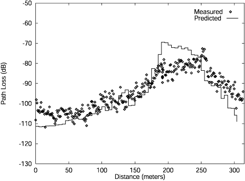
Figure 5: Path loss along Lynn St. for Transmitter Site 2B at 900 MHz. The path starts at Wilson Blvd. and ends at the Lee Hwy.
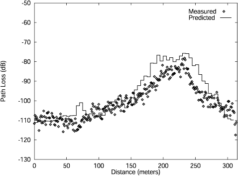
Figure 6: Path loss along Moore St. for Transmitter Site 2B at 900 MHz. The path starts at Wilson Blvd. and ends at the Lee Hwy.
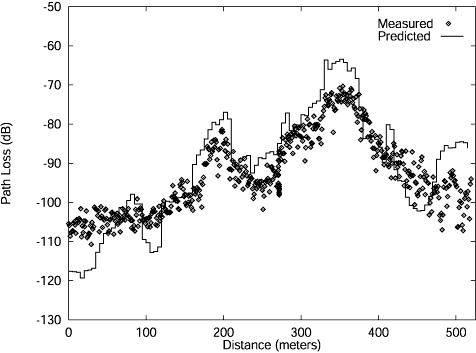
Figure 7: Path loss along Nash St./19th St. for Transmitter Site 4B at 900 MHz. The path starts at Wilson Blvd. and ends near site 2B.
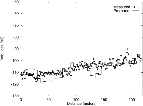
Figure 8: Path loss along Kent St. for Transmitter Site 4B at 900 MHz. The path starts at Wilson Blvd. and ends near site 2B.
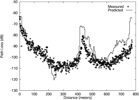
Figure 9: Path loss along 19th St./Colonial Terrace for Transmitter Site 7 at 900 MHz. The path goes around in a clockwise direction starting near Ode St. and ending at 19th St.
Some predictions made with the full 3D propagation model in the high-rise area are shown in Figure 10 and Figure 11.
Comparisons of the predicted to measured path loss for transmitter site 8 at 900 MHz are shown in Figure 12 and Figure 13. The agreement is quite good for most of the receiver locations. The free space (1/r?2) path loss is also shown in these plots. The pronounced effect that the buildings have on the signal strength can be seen in these figures. For example, there are many places where the signal strength is three orders of magnitude lower thant it would be in free space.
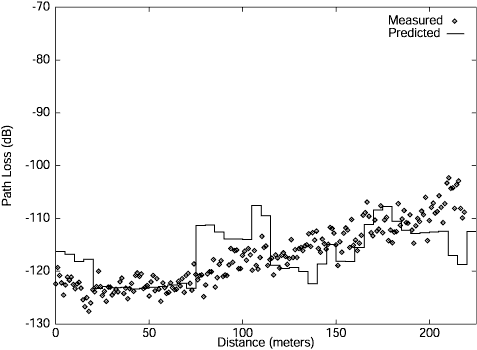
Figure 10: Path loss along Kent St. for Transmitter Site 6 at 1.9 GHz. The path starts at Wilson Blvd. and ends near transmitter site 2B.
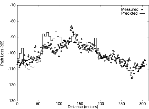
Figure 11: Path loss along Lynn St. for Transmitter Site 6 at 1.9 GHz. The path starts at Wilson Blvd. and ends near the Lee Hwy.
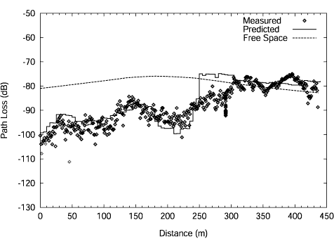
Figure 12: Path Loss along 19th St./Nash St. for Transmitter Site 8 at 900 MHz. The path starts near Wilson Blvd. and ends near transmitter site 2B.
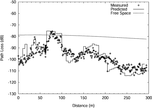
Figure 13: Path Loss along Moore St. for Transmitter Site 8 at 900 MHz. The path starts near the Lee Hwy. and ends at Wilson Blvd.
References
- S. C. Kim, B. J. Guarino, T. M. Willis, V. Erceg, S. J. Fortune, R. A. Valenzuela, L. W. Thomas, J.Ling and J. D. Moore, "Radio propagation measurements and prediction using three-dimensional ray tracing in urban environments at 908 MHz and 1.9 GHz," IEEE Trans. Veh. Technol., vol. 48, pp. 931-936, May 1999.

