- Products & Solutions
- Wireless InSite
- Communication Systems Analysis
Communication Systems Analysis
Calculate SINR, throughput, theoretical capacity, and bit error rate (BER) to visualize and assess wireless device performance.

Wireless InSite’s Communication Systems Analyzer uses the results from ray-tracing channel modeling simulations and applies post-processing calculations to predict a number of different communication metrics. These include SINR, throughput and capacity, bit error rate, and summary results that identify the best-performing base stations for each receiver point and provide the overall coverage from the system as a whole. Users with a MIMO license can additionally select from a number of MIMO techniques that can be applied to enhance the channel or create multiple data streams prior to performing the communication analysis (see below).
Setting up a Communication Systems for Analysis
Once a communication system is set up, a user can choose from three general types of analysis to assess its performance:
- Bit Error Rate (BER)
- Throughput
- Shannon Capacity
The first step for all these analyses is the calculation of noise, interference from other sources, and signal-to-interference-plus-noise ratios (SINR). For users with a MIMO license, there are additional calculations performed to apply MIMO techniques prior to beginning the communication analysis.
Interference and Noise Analysis
The first step in any analysis is to use channel data and noise specifications to determine signal power, interference, and noise. Noise power is determined from noise power density, signal bandwidth, and each receiver’s noise figure and threshold. Interference is determined using the received power from base stations within the system as well as any interferers (neighboring base stations outside the defined system). From these inputs, the analyzer determines quantities such as the total noise and interference power at each receiver point in the study, the signal-to-noise-ratio (SNR), the signal-to-interference-plus-noise ratio (SINR), and a number of other related quantities. Summary data is also collected, for example, determining the best SINR at each point and the base station from which that SINR was achieved.
Throughput and Capacity
Wireless InSite can predict the throughput and capacity (theoretical maximum data rate) for a channel from the bandwidth and SINR. It supports several different wireless access methods, including:
- 5GNR (FR1, FR2)
- LTE
- 802.11n, ac, ax
- User-defined table
User-defined tables can be used to define other access methods or to customize the selection of modulation and coding scheme as a function of SINR (often a vendor-specific relationship).
Once the wireless access method is selected, the user chooses from allowed bandwidths for carriers, and the analyzer computes the throughput based on data from literature, specifications from communication standards, and the calculated SINR for each channel in the communication analysis.

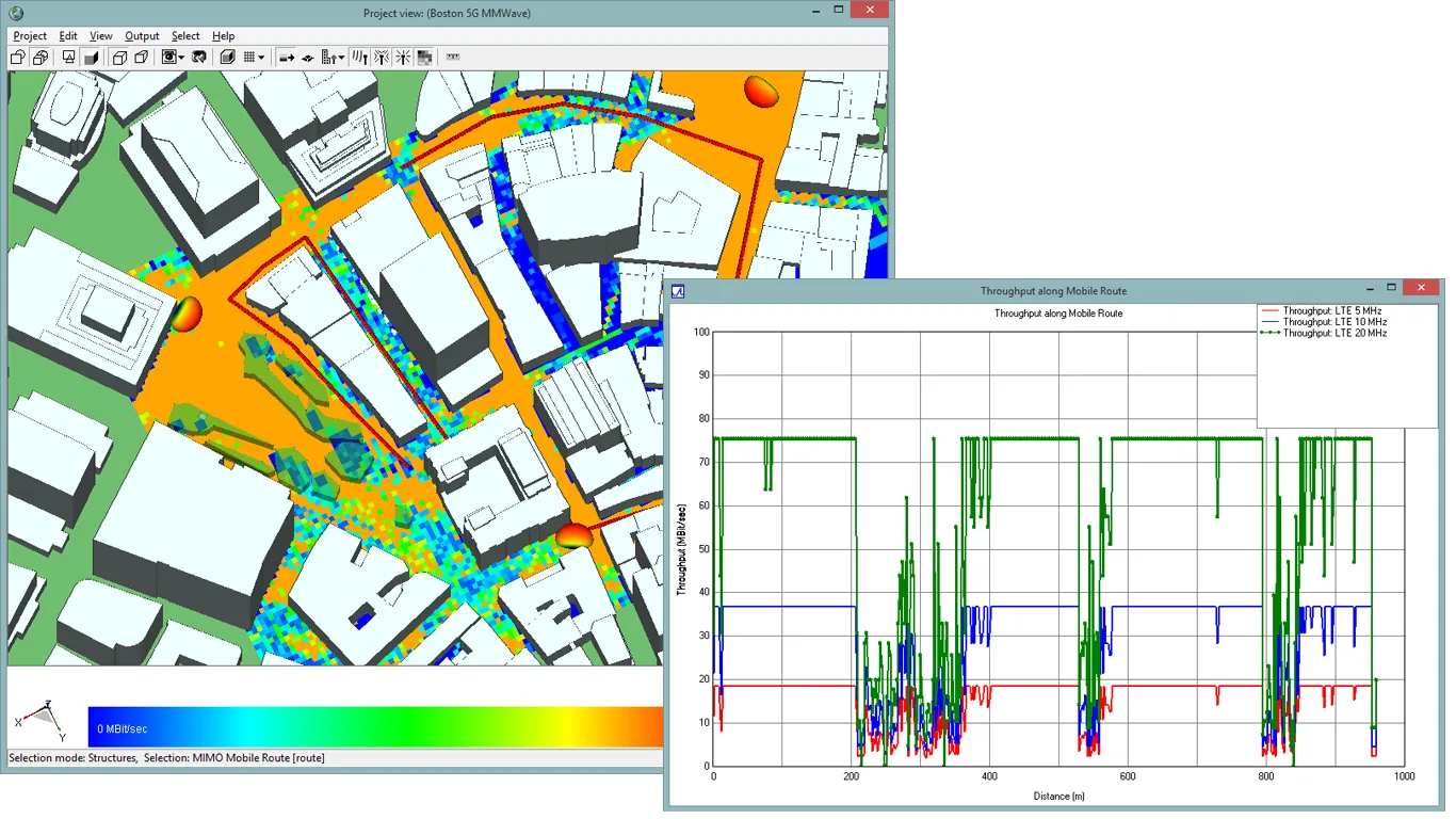
Wireless InSite throughput calculations for three different LTE bandwidths. Route through scene (red line) shows additional details of throughput reduction in areas where there are dropouts in coverage

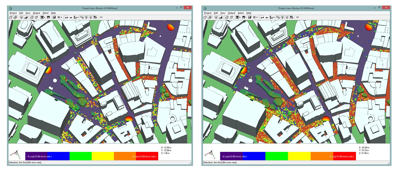
Comparison of Bit Error Rate for 4-QAM (left) and 256-QAM (right) shows high BER in a larger proportion of the coverage area when higher-order modulation is used.
Bit Error Rate
Wireless InSite offers three methods for bit error rate analysis:
-
AWGN: assumes an additive white Gaussian noise (AWGN) channel
-
Theoretical Fading: assumes a Rayleigh or Rician fading channel
-
Semi-Analytic: determined based on an analysis of the complex impulse response of the channel
The bit error rate calculation is heavily dependent on the selection of the modulation and coding scheme (e.g., quadrature amplitude modulation, or QAM) and the alphabet size (e.g., 64). It is also dependent on the SINR, the bandwidth, and for some of the methods, additional details about the channel characteristics, derived from the complex impulse response.
MIMO Beamforming, Spatial Multiplexing and Diversity
When a user has a MIMO license, several MIMO techniques are offered as options for any MIMO base station or UE that is present in the communication system. For 5G/6G base stations or WiFi access points in the system that have MIMO antennas (typically defined as transmitters), the user can choose one of following options:
- Adaptive beamforming using MRT
- Precoding/beamforming table (supports beamforming or diversity techniques)
- No beamforming/precoding
- Closed-loop spatial multiplexing (MxN MIMO) using singular value decomposition (SVD)
For receivers (UEs) that have MIMO antennas, the user can choose from these options:
- Selection combining (SC)
- Equal gain combining (EGC)
- Maximum ratio combining (MRC)
- Precoding/beamforming table
- Closed-loop spatial multiplexing (MxN MIMO) using singular value decomposition (SVD)
Each of these options takes advantage of spatial diversity in the MIMO antennas at the transmitter and receiver for each point-to-point link and attempts to enhance the performance using the specified techniques at each end, or in the case of SVD, coordinating from both ends of the link. The result will generally increase the SINR through beamforming or diversity, or it will provide multiple parallel data streams through spatial multiplexing. Throughput and BER calculations will then be applied to each of the resultant data streams for each point-to-point link in order to determine the results.
See MIMO Beamforming, Multiplexing and Diversity in Wireless InSite for more information.
Save time and reduce costs.
Contact Remcom today for a customized solution to your most complex electromagnetic challenges.
Request a Quote