FDTD Simulation: Optimizing an LTE Antenna's Matching Network
A simple antenna for LTE band operation is added to the PC board of a smartphone in XFdtd and the matching circuit is tuned for operation in multiple frequency bands. The components in the matching network are chosen to maximize system efficiency.
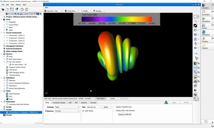
Figure 1 shows the antenna being used, which is a simple strip fed off center. It can be thought of as two back-to-back inverted L antennas of different “top” lengths, though the operating modes are more complicated than that. Figure 2 shows system efficiency for this antenna when fed directly and demonstrates that matching is required to improve performance.

Figure 1: LTE antenna without matching network.
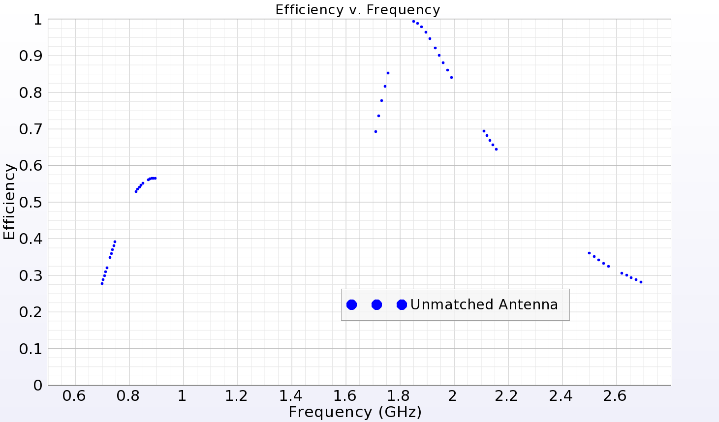
Figure 2: System efficiency of unmatched antenna.
Mobile phones are intended to work over multiple frequency bands defined by an operator. Table 1 outlines the required LTE bands for this example.
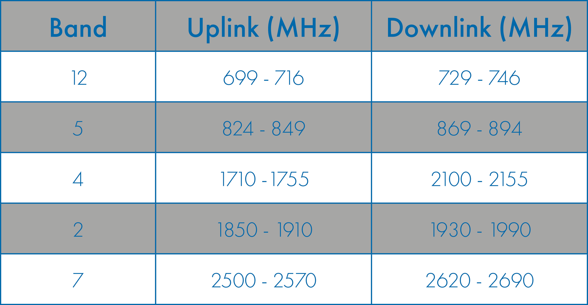
Table 1: Frequency bands defined by the operator.
In order to provide maximum power transfer and efficiency, a matching network is employed between the feed and the antenna. The design criteria goal is to produce an antenna and matching circuit that provide an average system efficiency of at least 65% over all of the bands of operation. In order to satisfy the design goals, the matching circuit of Figure 3 is chosen. Figure 4 shows the antenna and matching circuit in XF and Figure 5 shows the circuit layout in greater detail.
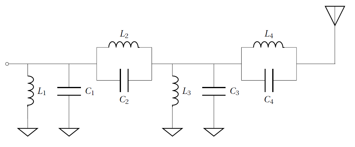
Figure 3: Schematic of matching network.

Figure 4: Layout of matching network.
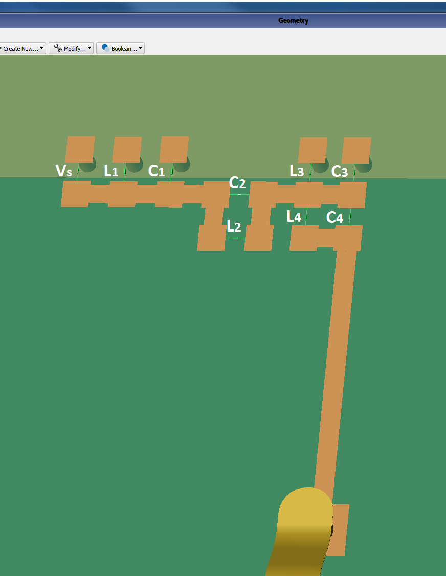
Figure 5: Details of matching network layout.
The goal in this case is to find a set of real capacitors and inductors manufactured by Murata that could be used in this mobile device’s matching circuit. Based on this application and the approximated size requirements from our physical circuit layout, the Murata GJM and GRM series capacitors in the 0603 size (0.6 x 0.3 mm), along with the LQP03TG, LQP03TN, LQP03TQ, and LQP03HQ series inductors are chosen as the candidate components. Because we are using several different component series, some of the capacitance and inductance values are repeated across multiple series. In order to accurately represent all of the components, the circuit optimization components are specified as a tunable definition and each Murata component is represented by a separate device definition.
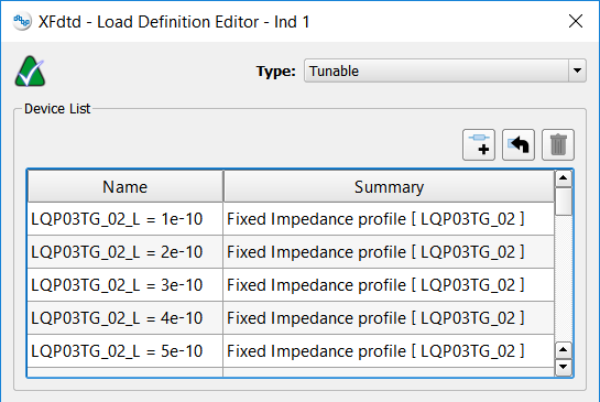
Figure 6: One of the component definitions after the MDIF has been imported.
Note: Rather than importing a single .s2p file for each Murata component and creating a new device definition each time, the s2p data for each series can be compiled into an MDIF file that can be imported to the tunable definition. XF will then automatically create a new device for each set of s2p data in the MDIF file, as shown in Figure 6.
XF’s Circuit Element Optimizer is used to characterize the system using XF’s full wave FDTD solver. The optimal components from each series are determined based on that characterization. As a result, the chosen component values and their Murata part numbers are provided in Table 2 and the corresponding system efficiency for the matched antenna is compared to the unmatched case, as seen in Figure 7.
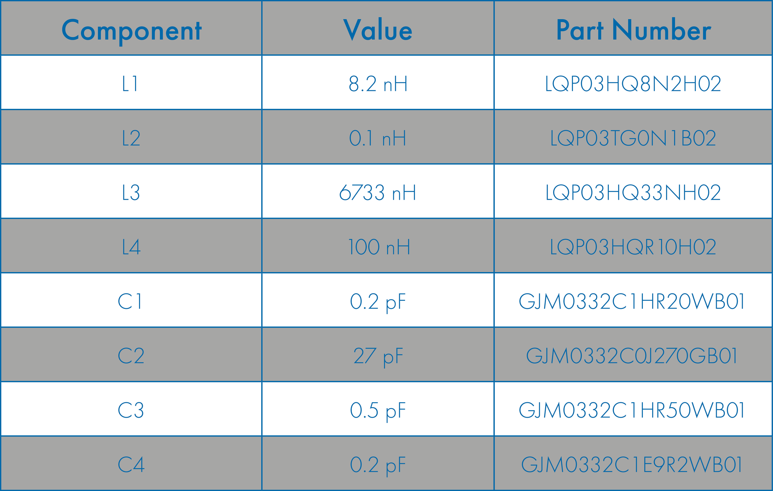
Table 2: Optimal circuit component values.
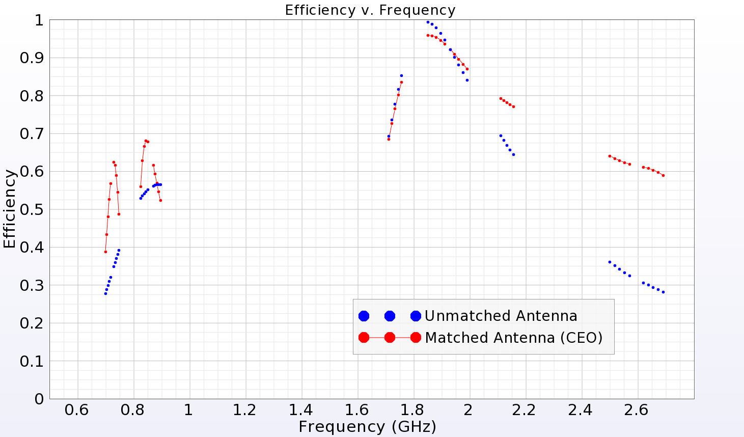
Figure 7: System efficiency of matched and unmatched antenna.
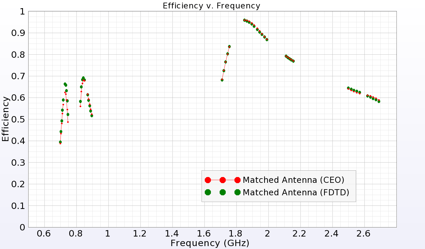
Figure 8: System efficiency of matched antenna, CEO and FDTD.
In order to further validate our results from the circuit optimization, the corresponding netlist files for each of the chosen Murata components are imported and used to define each component in our matching circuit, and an FDTD simulation is run. The FDTD simulation confirms the results we saw from the circuit optimization, as shown in Figure 8. Now that a set of suitable real circuit components is known, a working prototype can be built and the antenna performance can be measured in a lab to confirm the simulation results.
Request Project Files
Thank you for your interest in this application example. Please complete the form below to download the FDTD Simulation: Optimizing an LTE Antenna's Matching Network project files.
