Ternary Tree Loop Multiband Frequency Selective Surface
In this example a multiband frequency selective surface (FSS) is simulated with XFdtd. Simulated results are compared to measured results. The filter design and measured data are taken from [1].
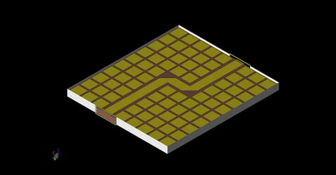
The frequency selective surface consists of a pattern of tripoles surrounded by ternary tree loops made of perfect electric conductor, Figure 1. Beneath the conductor layer is 76.2 μm thick polyethylene terephthalate resin with εr = 3.3. A simulation using the full dimensions of the physical device is too computationally complex to simulate. Instead, periodic boundary conditions are used to pattern the structure infinitely in all directions reducing the required resources to a manageable size. Energy was introduced into the space using a plane wave excitation. A near field sensor point was added to capture the electric field in order to compute the transmission.
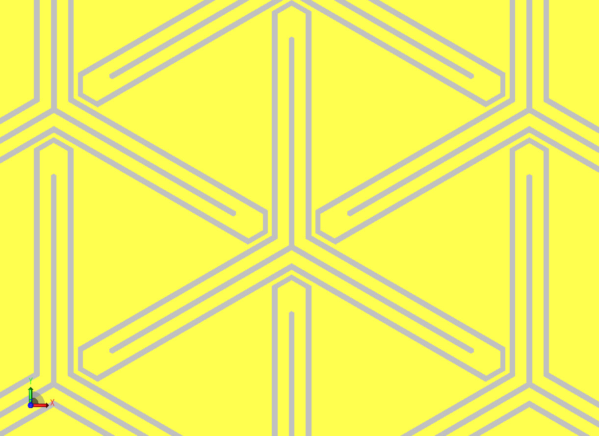
Figure 1: Geometry of the FSS.
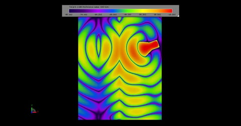
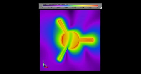
The simulation ran on an 8-core Intel i7 in 59 minutes and required 1.4 GB of RAM. The transmission was computed through scripting by dividing the frequency domain near field point output by the shape of the input waveform. The simulated transmission shows good agreement to the measurements, Figure 2. Figures 3-5 show field transmission being stopped at 0.885 GHz, 1.78 GHz and 2.45 GHz respectively. Figure 6 and Figure 7 show fields transmitting at 1.2 GHz and 2.07 GHz.
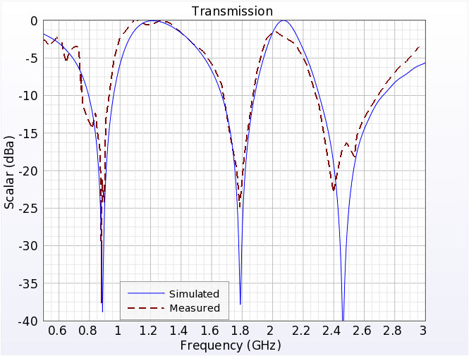
Figure 2: Measured and Simulated Transmission through the FSS vs frequency.
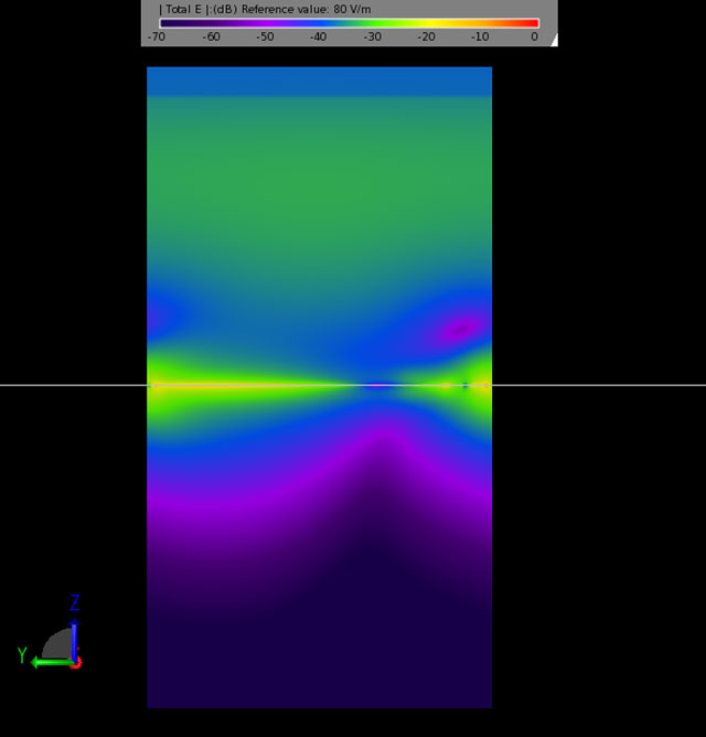
Figure 3: Electric field being blocked by the FSS at 0.885 GHz.
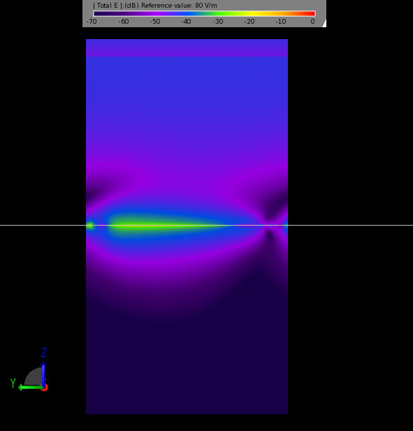
Figure 4: Electric field being blocked by the FSS at 1.78 GHz.
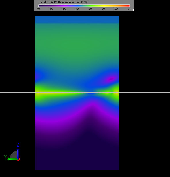
Figure 5: Electric field being blocked by the FSS at 2.45 GHz.
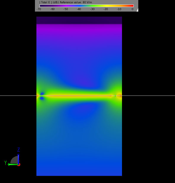
Figure 6: Electric field being transmitted through the FSS at 1.2 GHz.
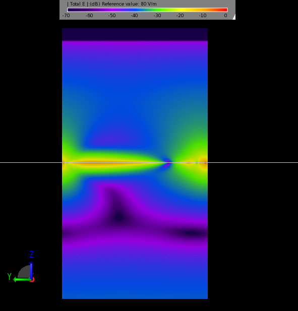
Figure 7: Electric field being transmitted through the FSS at 2.07 GHz.
References
-
D.-H. Kim and J.-I. Choi, Design of a Multiband Frequency Selective Surface, ETRI Journal, Volume 28, Number 4, August 2006, pp. 506-508.
Request Project Files
Thank you for your interest in this application example. Please complete the form below to download the Ternary Tree Loop Multiband Frequency Selective Surface project files.
