Wireless InSite Outdoor RF Propagation – Tutorial Series
When planning a wireless network, RF propagation experts need to understand the channel characteristics in complex dense environments. Effects such as multipath, antenna polarization, constructive and destructive interference, and more are essential for successful and optimal network performance. In addition, beamforming simulations can maximize the channel by weighting the H-matrix for MIMO systems. In this video tutorial series, we walk through a step-by-step outdoor RF propagation analysis using Wireless InSite MIMO.
Geometry Import and Materials:
Wireless InSite EM Propagation Software users can import many formats of 3D CAD geometry to construct an outdoor scene containing terrain, buildings, and foliage. Several of these formats, such as GeoTiff and Shapefile, allow for accurate geolocation of the geometry.
After importing the geometry layers, users can assign material properties, including permittivity, conductivity, and thickness to the geometry from a predefined library. Multi-layer dielectrics, Monte Carlo materials, and user-defined reflection and transmission coefficient materials (based on measurements) can also be assigned. Wireless InSite includes frequency-specific variants of common construction material properties such as glass, concrete, brick, and multi-layered drywall from 100 MHz to 100 GHz.
Waveforms, Antennas and Transmitter/Receiver Sets:
In this scenario, a 28 GHz waveform is transmitted from a 4x4 MIMO array using custom user-defined antenna gain patterns for each of the elements. The transmitting base station is placed near the corner of a building at 12 meters above the terrain and is rotated to point outward over an open area of the scene. A grid of receivers configured with half-wave dipole antennas is used to measure the coverage of the base station in the scene. Adjacent Path Generation (APG) is used as a runtime optimization on the receiver set to reduce the density of the receivers grid during the simulation and then extrapolate results to nearby receivers in the full-resolution grid.
Study Areas, Communication Systems, and Outputs:
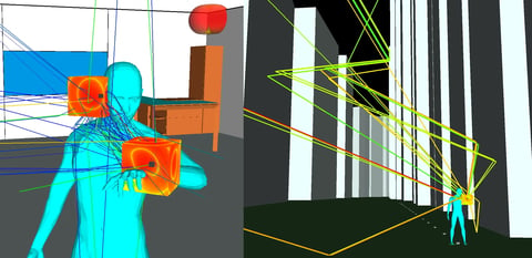
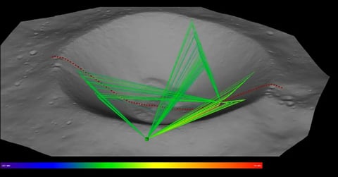
For outdoor propagation, Wireless InSite’s X3D GPU-enabled ray tracer is used. This ray tracer supports frequencies from 100 MHz to 100 GHz and for LOS up to 1 THz. Users have the ability to specify the ray spacing, number of reflections, transmissions, and diffractions for each generated ray. The tool generates ray paths using the shooting-and-bouncing ray technique (100% deterministic approach) based on the map data in the project. The rays generated are corrected using the exact path calculation algorithm to ensure they hit the center of the Rx point to accurately capture power and phase. Users are provided with core ray path data, which also includes the effect of phase changes from the environment and antenna polarization. In this scenario, the Weissberger Model is used for calculating foliage attenuation.
Wireless InSite’s built-in Communication Systems Analysis tool lets users generate BER, throughput, and capacity computations on the core outputs to generate RSSI or impact of interference between transmitters on overall coverage. These outputs are available for WiFi, LTE, 5G NR, and user-defined protocols.
For MIMO systems, beyond SVD, beamforming techniques including custom weighted tables are available to apply weighting factors on the generated channel matrix (H-matrix). For the UE side, combination techniques like selection combining and MRC are available.


