- Methods
- Finite-Difference Time-Domain Method (FDTD)
The FDTD Method for Electromagnetic Simulation
The FDTD approach offers excellent scaling performance of the method as the problem size grows. As the number of unknowns increases, the FDTD approach quickly outpaces other methods in efficiency.
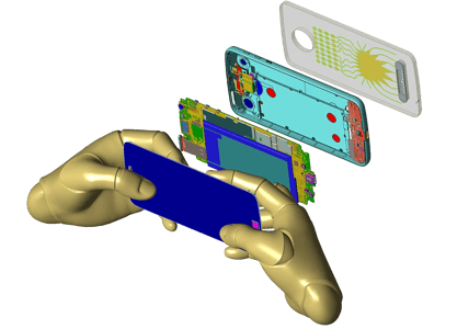
Mobile phone model provided courtesy of Motorola Mobility, LLC/Lenovo.
Why Use FDTD Simulation Software?
While many electromagnetic simulation techniques are applied in the frequency-domain, FDTD solves Maxwell’s equations in the time domain. This means that the calculation of the electromagnetic field values progresses at discrete steps in time. One benefit of the time domain approach is that it gives broadband output from a single execution of the program; however, the main reason for using the FDTD approach is the excellent scaling performance of the method as the problem size grows. As the number of unknowns increases, the FDTD approach quickly outpaces other methods in efficiency. FDTD has also been identified as the preferred method for performing electromagnetic simulations for biological effects from wireless devices [1]. The FDTD method has been shown to be the most efficient approach and provides accurate results of the field penetration into biological tissues.
A Brief Summary - FDTD Simulation Basics
In the FDTD approach, both space and time are divided into discrete segments. Space is segmented into box-shaped cells, which are small compared to the wavelength. The electric fields are located on the edges of the box and the magnetic fields are positioned on the faces as shown in Figure 1. This orientation of the fields is known as the Yee cell [2, p. 37] and is the basis for FDTD. Time is quantized into small steps where each step represents the time required for the field to travel from one cell to the next. Given the offset in space of the magnetic fields from the electric fields, the values of the field with respect to time are also offset. The electric and magnetic fields are updated using a leapfrog scheme where first the electric fields, then the magnetic, are computed at each step in time.
When many FDTD cells are combined together to form a three-dimensional volume, the result is an FDTD grid or mesh. Each FDTD cell will overlap edges and faces with its neighbors, so by convention each cell will have three electric fields that begin at a common node associated with it. The electric fields at the other nine edges of the FDTD cell will belong to other, adjacent cells. Each cell will also have three magnetic fields originating on the faces of the cell adjacent to the common node of the electric fields as shown in Figure 1.
Within the mesh, materials such as conductors or dielectrics can be added by changing the equations for computing the fields at given locations. For example, to add a perfectly conducting wire segment to a cell edge, the equation for computing the electric field can be replaced by simply setting the field to zero since the electric field in a perfect conductor is identically zero. By joining numerous end-to-end cell edges defined as perfectly conducting material, a wire can be formed. Introducing other materials or other configurations is handled in a similar manner and each may be applied to either the electric or magnetic fields depending on the characteristics of the material. By associating many cell edges with materials, a geometrical structure can be formed within the FDTD grid such as the dielectric sphere shown in Figure 2. Each small box shown in the figure represents one FDTD cell.
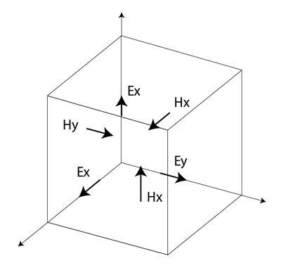
Figure 1: The Yee cell with labeled field components
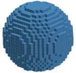
Figure 2: A dielectric sphere as meshed in a traditional FDTD grid with staircasing. The individual cell edges (electric field locations) are displayed as overlapping grid lines.
The cell size, the dimensions of the small box, is the most important constraint in any FDTD simulation since it determines not only the step size in time, but also the upper frequency limit for the calculation. A general rule of thumb sets the minimum resolution, and thus the upper frequency limit, at ten cells per wavelength. In practice the cell size will often be smaller than this in order to resolve dimensions and features of the structure to be simulated such as the thickness of a substrate or the length of a wire.
An excitation may be applied to an FDTD simulation in many different ways. One method emulates exciting a geometry at discrete locations by applying a sampled waveform to the field update equation at one or more locations. At each step in time, the value of the waveform over that time period is added into the field value. The surrounding fields will propagate the introduced waveform throughout the FDTD grid appropriately, depending on the characteristics of each cell. A calculation must continue until a state of convergence has been reached. This typically means that all field values have decayed to essentially zero (at least 60dB down from the peak) or a steady-state condition has been reached.
Cell Staircasing Advancements
Traditionally, staircased FDTD cells are considered cumbersome and inefficient at resolving curved surfaces or highly varying fields. Advancements in FDTD allow for conformal meshes and singularity correction.
The cubicle Yee cell of Figure 1 can in general be rectangular. The spacings between cells in the x, y, and z-directions can vary throughout the problem space. This allows more cell edges to be placed in regions of strong fields, such as around small features of highly conductive material. Within a cell, the standard update equations of FDTD may be refined in many ways, for example to allow for wires that are thinner than a cell size or to calculate the strong fields on the edges of conductors such as microstrip lines. Another refinement can allow for objects whose surface intersects the cell at arbitrary angles with respect to the principle axes. These “conformal” cells can be further refined to account for curvature of the object surface within the volume of the cell.
Figure 3 shows the geometry of a portion of a mobile phone. For clarity, the visibility of many of the parts, including the outer case, has been turned off to show the region near the antenna. A small portion of the FDTD mesh of the phone is shown in Figure 4a using simple rectangular cells. In Figure 4b the same part of the phone mesh is shown, this time using a type of conformal treatment for cells which contain portions of the surface of an object. Figure 5 shows a larger view of the surfaces of the conformal mesh.
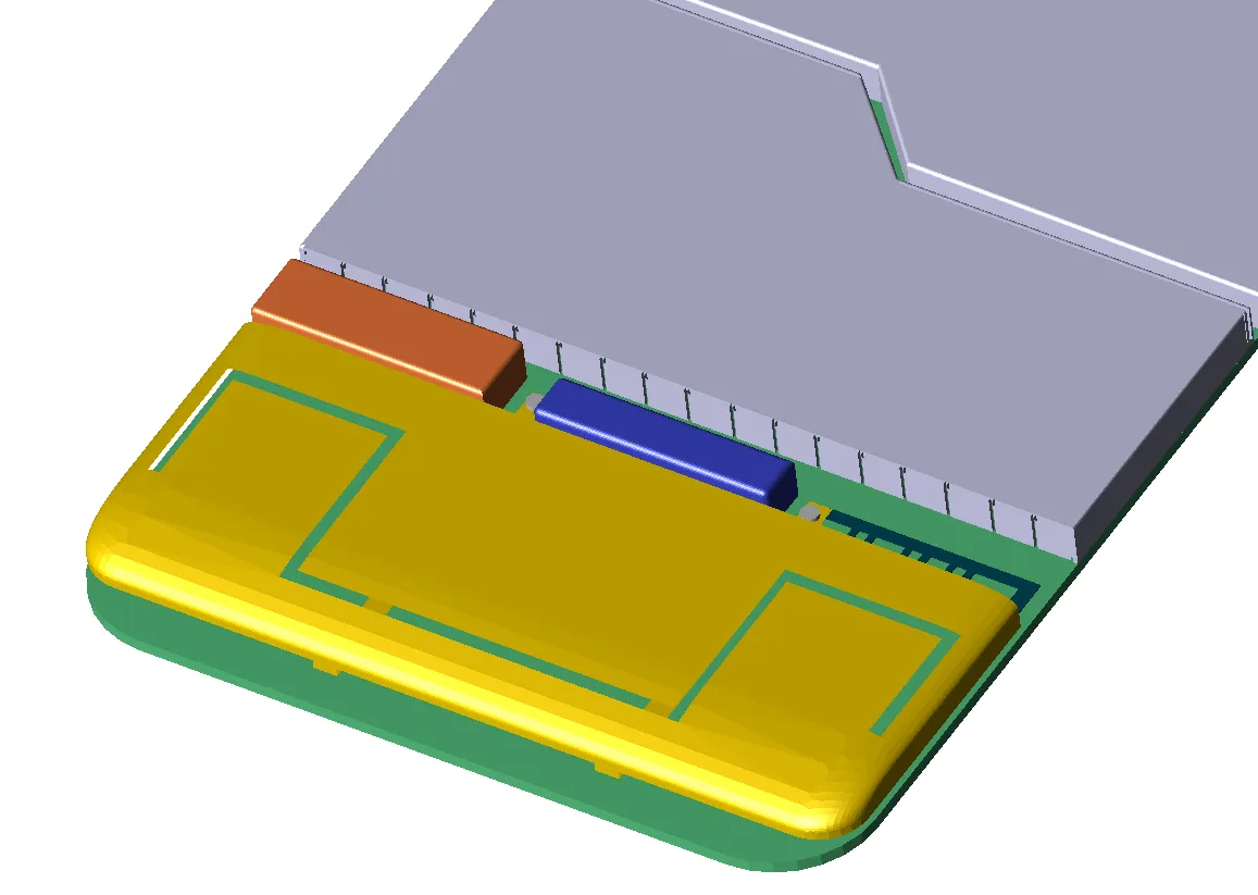
Figure 3: Antenna section of mobile phone.
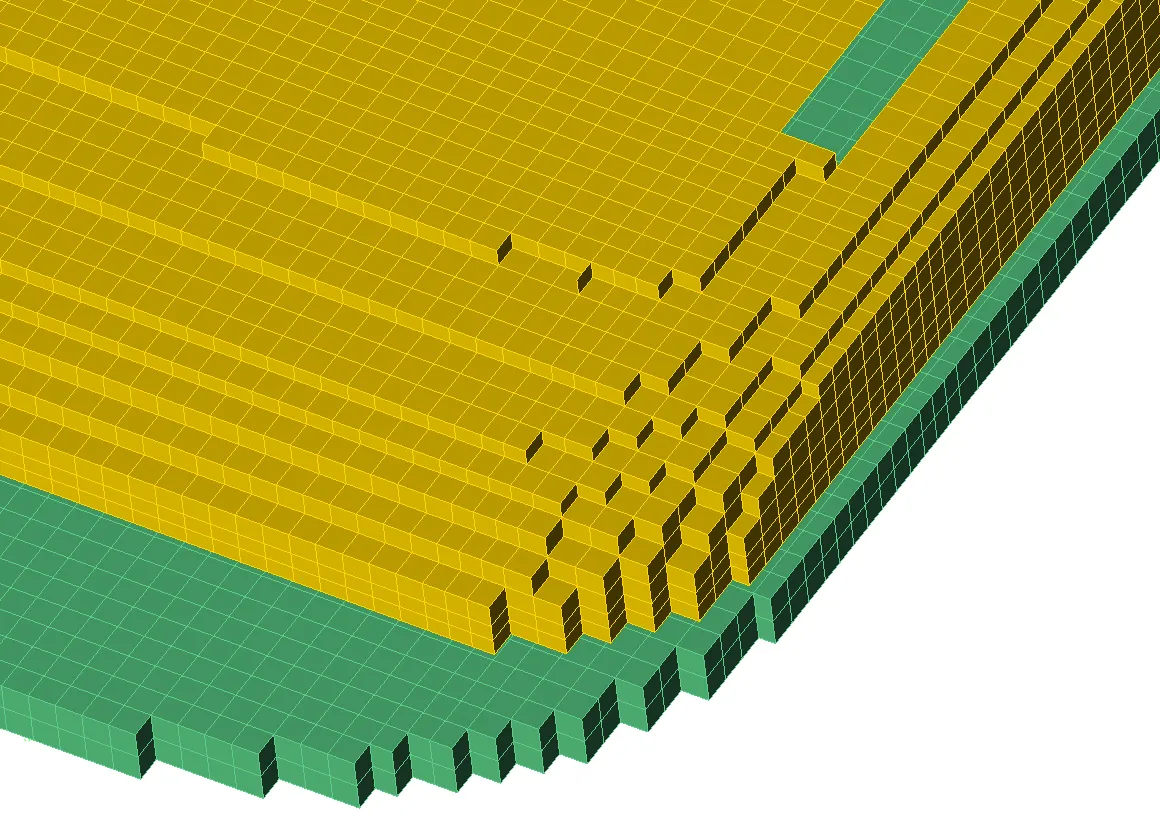
Figure 4a: Mesh view of corner of antenna using simple rectangular mesh.
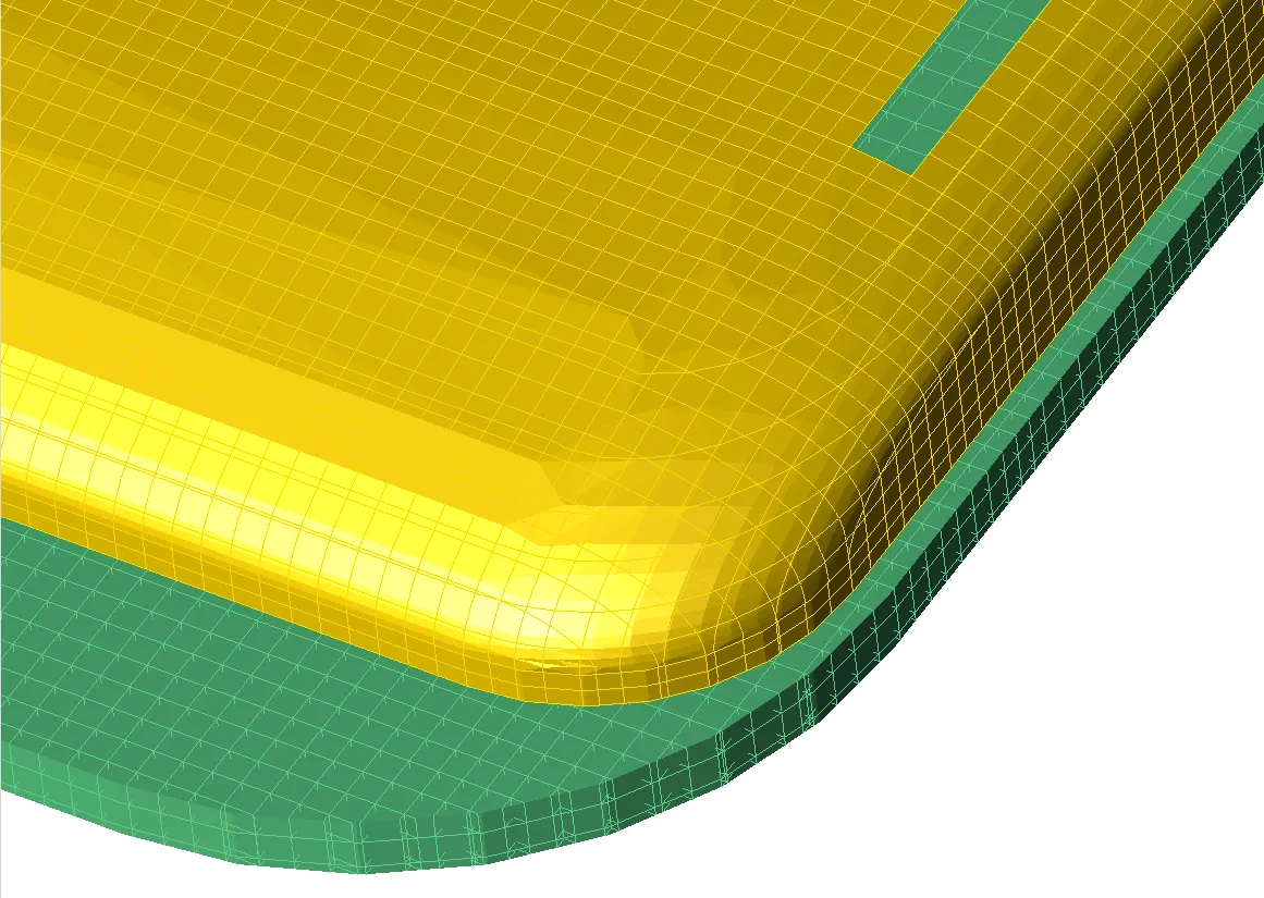
Figure 4b: Mesh view of corner of antenna with conformal mesh.
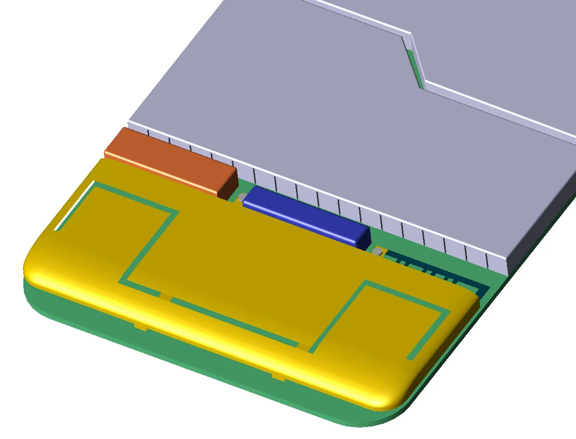
Figure 5: Conformal mesh of mobile phone antenna.
Materials
FDTD simulation software is capable of simulating a wide variety of electric and magnetic materials. The most basic material of course is free space. All FDTD cells are initialized as free space and the fields at all cell edges are updated using the free space equations unless another material is added to replace the free space.
Perfectly conducting electric and magnetic materials are simulated by setting the electric or magnetic field to zero for any cell edges located within these materials. Because of the simplicity of the calculation for these materials, it is better to use a perfect conductor rather than a real conductor whenever feasible. Conductors such as copper can be simulated in FDTD, but since the equations for computing the fields in copper material are more complicated than those for a perfect conductor, the calculation will take longer. Of course for cases where only a small percentage of the FDTD cells are defined as a conductor, the difference in execution time will hardly be noticeable.
Frequency independent dielectric and magnetic materials are defined by their constitutive parameters of relative permittivity and conductivity or loss tangent for the electrical material, or relative permeability and magnetic conductivity for the magnetic material. In many cases, even when performing a broadband calculation, these materials are appropriate since the parameters do not vary significantly over the frequency range.
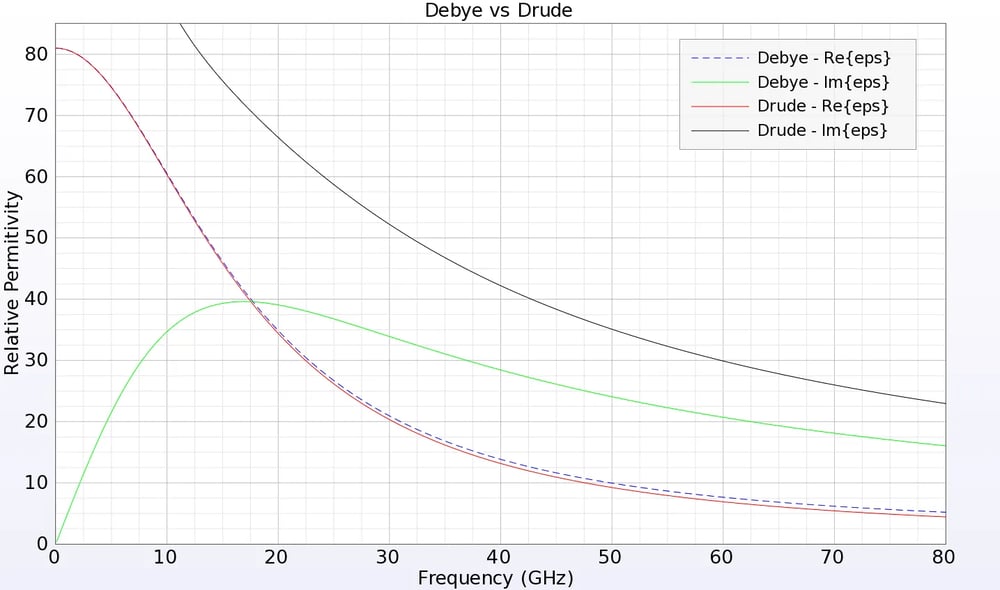
In some cases a frequency independent material is not appropriate and instead a frequency dependent, or dispersive, material should be substituted. Some common examples of frequency dependent materials are high water content materials such as human tissues, metals when excited at optical frequencies, and dielectrics over wide bandwidths. Included in XFdtd is the capability to simulate electric and magnetic Debye and Drude materials such as plasmas, Lorentz materials, and anisotropic magnetic ferrites, as well as frequency independent anisotropic dielectrics. These materials may have permittivities or permeabilities that are negative at some frequencies, making them effective for simulating metamaterials macroscopically. FDTD is also particularly effective at simulating nonlinear materials, several of which are included in XFdtd.
Near-Zone Versus Far-Zone
For any given calculation the geometry of the structure being simulated is defined by setting the cell edges at specific locations to certain materials. The entire FDTD geometry space, commonly called the grid or the mesh, is composed of a three dimensional block of these cells. This three dimensional volume is considered to be the near-zone region in FDTD in terms of the data storage. The field value at any edge in the FDTD grid may be observed as a function of time by saving a “near-zone” point in XFdtd. Other types of data such as steady-state field magnitudes, specific absorption rates, S-parameters, or impedance may be stored as well for appropriate points, surfaces, and volumes within the grid.
It is possible to make an FDTD grid that is large enough to allow sampling of points in the far field of a geometry. In general this will be extremely costly in terms of computer memory and calculation time since the number of unknowns (cells) will most likely be large. Note that each FDTD cell has a maximum size of one-tenth of a wavelength, so moving many wavelengths away from a structure will require a large number of cells. In most cases this is not an appropriate method of monitoring far field results.
A more practical method for transforming field values to the far-zone and for calculations of radiation gain or radar scattering patterns is to use a transformation to convert the near-zone values in the FDTD grid into a far field value at some location away from the grid. This is done by enclosing the geometry in a box and storing the fields on the outer faces of this box for general far-zone problems. The faces of the box are located five FDTD cells from each outer edge of the FDTD grid. For the transformation to be valid, all parts of the FDTD geometry must be contained within the box.
The polar coordinate system used in XFdtd is defined with the azimuthal (phi) angle referenced from the x-axis and the elevation (theta) angle referenced from the z-axis, as shown in Figure 6. This coordinate system is used for locating far-zone positions and for defining the incident plane wave direction.
.webp?width=269&height=254&name=image-asset%20(4).webp)
Figure 6: Polar coordinate system used for far-zone and incident plane wave directions.
Broadband And Steady-State Calculations
Generally a broadband calculation is performed with FDTD since a single calculation can yield results for a wide range of frequencies without requiring extra computer resources. When data at particular frequencies are required, steady-state data may be computed from the broadband calculation by means of a Fourier transform.
Common examples of data vs frequency include antenna patterns at specific frequencies, biological applications such as the Specific Absorption Rate (SAR), electric and magnetic field magnitudes, magnetic flux magnitudes, conduction currents, and “circuit” type information such as S-Parameters, group delay, impedance, power, efficiency, etc.
Sinusoidal excitation may be desired in certain occasional cases, such as when avoiding a strong resonance near, but outside of, the frequency range of interest.
Outer Radiation Boundaries
A three-dimensional grid of cells forms the FDTD geometry and the fields updated at every cell location are dependent on the neighboring fields. However, due to memory limitations the grid must end at some point and because of this, the fields on the outer edges of the grid cannot be updated correctly. To correct this situation, outer radiation boundary conditions are applied at the edges of the FDTD grid.
The outer radiation boundary is a method for absorbing fields propagating from the FDTD grid toward the boundary. By absorbing these fields, the grid appears to extend forever. The performance of the outer boundaries is an important factor in the accuracy of an FDTD calculation and care should be taken to correctly use them.
In some cases a reflecting boundary rather than an absorbing one is preferred. A perfectly conducting boundary (either electric or magnetic) may be used to image the fields in an FDTD calculation to take advantage of problem symmetries. A periodic boundary condition is useful for simulating a single unit cell of a large symmetrical geometry.
Computer Resources
FDTD is a computationally intensive method and most reasonable calculations will need a fast computer and at least a few Gigabytes of computer memory. For most applications it is fairly simple to estimate the amount of computer memory required for a calculation. The most important factor for the memory usage, and in large part the run time, is the number of FDTD cells used to represent the structure under test. Each FDTD cell has six field values associated with it: three electric fields and three magnetic fields. Additionally each cell has six flags associated with it to indicate the material type present at each of the six field locations. The field values are real numbers, each four bytes in length, while the flags may each be one byte. This gives a memory usage per FDTD cell of 24 bytes for fields and 6 bytes for flags for a total of 30 bytes. To estimate the total memory required, in bytes, simply multiply the number of FDTD cells by the 30 bytes per cell value. There is some overhead in the calculation, but it is generally quite small. One notable exception is the broadband far-zone angles that allocate six one dimensional real value arrays per direction.
Estimating the execution time of an FDTD calculation is more complicated since performance of computer processors varies. One method of estimating is to compute the total number of operations to be performed. There are about 80 operations per cell, per time step during the FDTD calculations. The total number of operations is found from the product of the number of cells, the number of time steps, and the factor of 80 operations per cell, per time step.
If a value of the floating-point performance of the processor is known, a value for execution time can be computed. In general though, a better estimating method is to determine the execution time of a simple problem on a given computer and then scale the time by the ratio of the number of operations between the desired calculation and the simple one.
There are many ways to increase computation speed of FDTD, though some will require considerable effort to program. Some of the most effective are to use multiple CPUs of a computer in parallel, use multiple computers in parallel, optimize computation loops for cache, or take advantage of parallel methods on CPUs such as SSE and AVX. FDTD software is especially well suited to computation on GPU processors as the notion of many cells performing a relatively small number of update algorithms in parallel fits well with the methods developed for updating video displays.
References
-
C95.3.2002, “Recommended Practice for Measurements and Computations with Respect to Human Exposure to Radio Frequency Electromagnetic Fields, 100kHz to 300GHz,” IEEE Standards and Coordinating Committee 28 on Non-Ionizing Radiation Hazards, April 2002.
-
K. S. Kunz and R. J. Luebbers, “The Finite Difference Time Domain Method for Electromagnetics,” Boca Raton, FL: CRC Press, 1993.
Application Examples
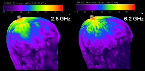
XFdtd SAR Simulations of a Mock Brain Computer Implant
This example shows Specific Absorption Rate (SAR) simulations for a first approximation Brain Computer Implant (BCI). It was generated using an open-source and anonymized data set of patient head models that includes five tissue compartments (scalp, skull, CSF, grey and white matter).
Explore Resource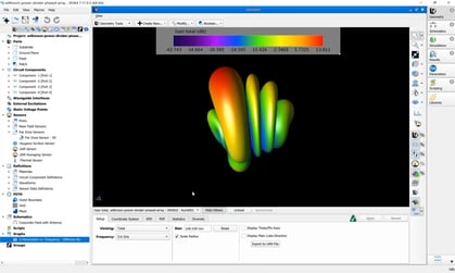
Publications
Mastering XFdtd’s Schematic Editor: A Comprehensive Overview
Dive into the capabilities of XFdtd’s schematic editor and discover how it transforms schematic creation, analysis, and optimization in engineering.
Explore Resource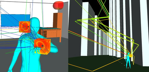
Publications
Breaking Boundaries in Wireless Communication: Simulating Animated, On-Body RF Propagation
This paper discusses how RF propagation simulations empower engineers in the design and development of wireless devices for body-worn applications.
Explore ResourceSave time and reduce costs.
Contact Remcom today for a customized solution to your most complex electromagnetic challenges.
Request a Quote